The dimensional parameters of a ribbon mixer serve as the fundamental input criteria for equipment selection and process layout. In engineering practice, the term “dimensions” encompasses three interrelated yet distinct aspects: volumetric capacity (which determines batch processing capacity), external geometric dimensions (which determine the installation footprint and required headroom), and the dimensions of internal moving parts (which determine the mixing range and uniformity). Together, these three aspects form a comprehensive dimensional profile of the ribbon mixer.
Ⅰ. Volume Specifications: Nominal Dimensions vs. Actual Capacity
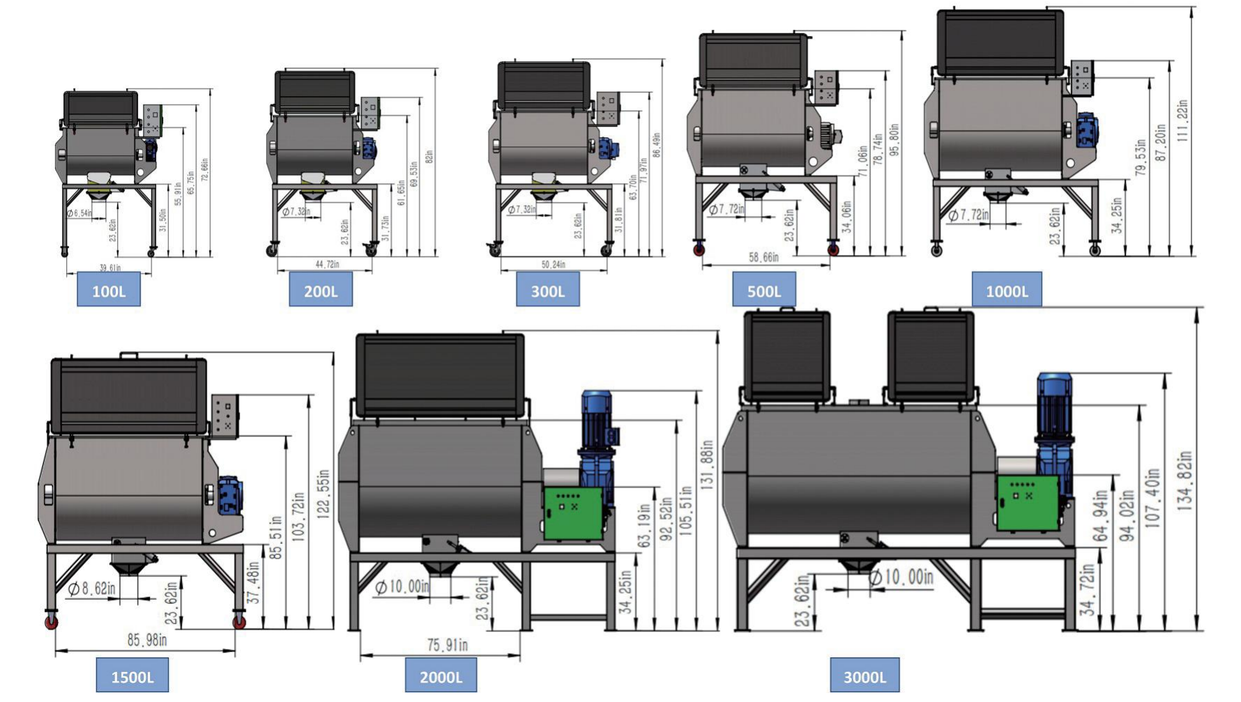
The model designations for ribbon mixers are typically based on the gross volume, which refers to the geometric volume of the internal space within the U-shaped trough of the mixing chamber, measured in liters (L) or cubic meters (m³). Common specifications range from 50-liter laboratory models to 30,000-liter industrial-scale units.
It is important to strictly distinguish this from the working volume, which refers to the volume occupied by the material during actual operation. Due to the requirement for free space at the top imposed by the mixing principle of ribbon mixers, a recommended fill rate of 40% to 70% of the gross volume is advised, with a typical design value of 60%. This means that a machine with a gross volume of 3,000 L has an actual batch processing capacity of approximately 1,800 L of material.
This constraint stems from the dimensional characteristics of the screw ribbon structure: as the inner and outer ribbons rotate, they must push the material from both ends toward the center or from the center toward both ends, while simultaneously creating radial tumbling. If the fill rate is too high, the material at the top will exceed the effective range of the ribbons and be unable to participate in the convective motion, directly affecting mixing uniformity.
II.External Dimensions: Length, Width, Height, and Space Constraints
The ribbon mixer features a horizontal design, and its external dimensions are determined by the following geometric parameters:
Length (L): Determined by the length of the mixing vessel and the axial installation dimensions of the end plates, bearing housings, and gear reducer
Width (W): Determined by the outer width of the U-shaped trough and the lateral projections of the motor and gear reducer
Height (H): Determined by the distance from the bottom of the trough to the top cover, plus the structural height of the bottom discharge valve and the top feed inlet
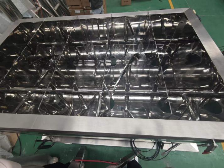
III.Dimensions of Internal Moving Parts: Screw Blade Diameter and Pitch
The dimensional parameters of the screw blades themselves directly determine the scope of the mixing action:
Screw Blade Outer Diameter: Determines the extent of radial tumbling of the material. The larger the outer diameter, the thicker the layer of material moved by a single rotation. Typically, the screw blade outer diameter is slightly smaller than the inner width of the U-shaped trough, with the clearance between the blade and the trough body maintained between 3 and 10 mm to prevent material jamming.
Pitch: The pitch of the inner and outer screw flights determines the axial distance the material is pushed with each rotation. In typical designs, the ratio of pitch to screw flight diameter is 0.8–1.2. A smaller pitch generates stronger shear forces, making it suitable for materials prone to agglomeration; a larger pitch increases the axial conveying speed, making it suitable for materials with good flowability.
The inner and outer screw flights typically employ a double-layer, counter-rotating configuration: the outer flights push the material toward one end, while the inner flights push in the opposite direction, achieving convective mixing throughout the entire drum. The dimensional difference between the two sets of flights (the inner flight diameter is typically 0.4 to 0.6 times that of the outer flight) provides the driving force for radial material movement.
Post time: Jun-03-2026